
Deck Building Guide
For many homeowners, the construction of a deck is the ideal do-it-yourself project: but sometimes, decks aren’t as simple as they look. Our building inspectors have gathered some pointers and tips to help homeowners and contractors build better decks. Throughout this guide it is assumed that the deck being planned is raised off the ground, and attached to a house. (The basic principles outlined here apply to most other decks.)
Step 1: determine joist length
Determine how far from the house the deck’s main supporting beam will be. This is the most critical measurement of all, because this ties into what kind of joist system and what kind of beam system is necessary. This is also going to be your basic joist span figure.
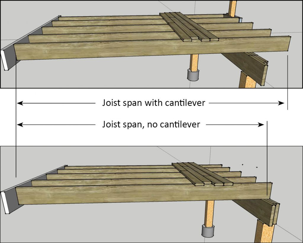
This distance should also include the length of any cantilever (length of joists beyond supporting beam.) Why? A cantilevered deck allows most surface area for potential load – be that people, or snow. A bulk of that load must be carried by the beam: so you need to determine the total distance from the building to the end of the deck.
Step 2: determine post spacing

The sturdier the beam, the further apart the posts can be placed. Alternately, the further apart the posts, the sturdier the beam must be.
Determine the beam construction. The sturdier the beam, the further apart the posts can be placed. The table shown here will help guide builders to understand post-spacing and beam construction combinations will work for each situation. Specifying the beam construction is simply a factor of determining how much the beam is supporting (in other words, the joist span from the house, determined in Step 1), which in turn will give information as to how far apart the posts can be.
These tables presume use of SPF lumber.
| Three-ply beams | Maximum post separation | ||
| Joist length | 2×8 | 2×10 | 2×12 |
| 8 | 11’0” | 14’0” | 17’1”* |
| 10 | 10’2” | 13’0” | 15’9” |
| 12 | 9’7” | 12’3” | 14’4” |
| 14 | 9’1” | 11’6” | 13’4” |
| 16 | 8’9” | 10’9” | 12’5” |
| Four-ply beams | Maximum post separation | ||
| Joist length | 2×8 | 2×10 | 2×12 |
| 8 | 12’1’ | 15’5” | 18’6”* |
| 10 | 11’3” | 14’4” | 17’5”* |
| 12 | 10’7” | 13’6” | 16’5”* |
| 14 | 10’0” | 12’10” | 15’4” |
| 16 | 9’7” | 12’3” | 14’4” |
* It should be noted that post spans greater than 15’8″ are not advised, because of challenges splicing beams. In such cases, it may be best to look at an engineered (LVL) beam instead.
Thinking about splicing a beam? Check here.
Step 3: Determine post size
The minimum allowed post bearing width is 5½”x5½” (usually called a 6×6). If you have opted for a four-ply beam, then a larger 8×8 post (again, actually 7½” square) posts will be necessary. Site-built posts may be built by laminating dimensional lumber. In this case, each piece of lumber must run fully from the underside of the beam to the supporting foundation element.
Step 4: Determine the foundation/support
Foundations are required to support posts, and must be a minimum of 4’ below grade to avoid the potential of frost heaves. Options include contractor-installed screw piles, frost walls, and sonotubes (round cardboard forms) installed either on site-built footings or on plastic forms. So-called “deck blocks” are not permitted for any deck attached to a structure. Please note that some of the inexpensive “do-it-yourself” screw piles are not permitted: they have not met Canadian standards for testing, and they only allow a 4×4 post.
Step 5: Determine joist size and spacing

To determine the distance between facing sides, simply subtract 1½”.
Determine joist size and spacing, using the tables below. In most cases, decks are exposed to snow loads, so table (C) is the one to use.
Alternately, if the deck will be covered with a roof, tables A or B can be used – please consult with us about rafter spacing for roofed decks if not using engineered trusses). If you plan to have a cantilever (a portion of the deck hanging out beyond the exterior beam) count the entire joist length, including the part that hangs over the beam.
Joist span tables (SPF lumber)
| TABLE A: Covered, decking only | |||
| 12” OC | 16” OC | 24” OC | |
| 2×6 | 10’4” | 8’11” | 8’2” |
| 2×8 | 11’7” | 11’ | 10’6” |
| 2×10 | 13’8” | 13 | 12’4” |
| 2×12 | 15’7” | 14’10” | 14’1” |
| TABLE B: Covered, with bridging | |||
| 12” OC | 16” OC | 24” OC | |
| 2×6 | 10’10” | 9’7” | 8’7” |
| 2×8 | 13’1” | 11’7” | 11’ |
| 2×10 | 15’3” | 13’8” | 13’ |
| 2×12 | 16’5”* | 15’7” | 14’10” |
| Uncovered (exposed to snow) | |||
| 12” OC | 16” OC | 24” OC | |
| 2×6 | 9’7” | 8’11” | 7’10” |
| 2×8 | 11’7” | 11’ | 10’3” |
| 2×10 | 13’8” | 13 | 12’4” |
| 2×12 | 15’7” | 14’10” | 14’1” |
The graphs here show 24” spacing, but on most decks this is unwise: that’s because the standard 1” deck board (especially 4” wide) will bend and flex to some degree under normal footsteps. Use 24” spacing for solid floors, not for strapped deck floors.
More on cantilevers

The Canadian Wood Council (which produces material that forms much of the wood-framed building codes in Canada) states that a cantilever should depend on the size of the lumber used, and be no more than 60 cm (24”) unless designed by an engineer.
2×6, 2×8: 16” maximum.
Step 6: Flashing and ledger installation

The most common way to attach a deck to a house (or other structure) is by first attaching lumber horizontally to the sill plate or studs of the existing building. This is called a ledger board. Code allows for nothing more than ledgers nailed to framing, however, this is strongly discouraged. The best practice is to attach the ledger using lag bolts or special through-bolts.
This area presents a risk for water penetration, especially in decks built onto existing houses as part of renovations. The illustration below shows best practices for flashing and sealing at the ledger.
The illustration shown here depicts a plastic “Z” flashing, but a peel-and-stick flashing tape could also be used: these products meet or exceed Code required standards and have been proven quite effective.
Step 7: Guards and guard support

What most folks call “rails,” building inspectors and construction professionals call “guards.” They’re designed to prevent people from falling off a deck. They’re usually accompanied by balusters (vertical rails.) The balusters must be no more than 10 cm (4”) apart. Guards must be 36” high for low-level decks, or 42” high if the drop on the other side is 6’ or more.
The answer to a question we receive often: yes, you can use 4×4 posts to support guards with. Do not consider surface-mounting these posts: they will not offer sufficient strength. The best plan is to have these posts drop down to the same level as the underside of the joists, and frame them in with a blocked-in crossmember (see illustration). Ideally, this can be done so that the post is framed by an outside, inside and joist face, so that it abuts three supporting timbers for extra strength. This should all be done before the installation of deck boards.
Other design considerations
Structural attachments (joists to ledgers, beams, blocking, tie-ins for posts to support guards) must be attached with nails or specially designed screws. Deck screws must not be used for structural attachment.

Specially designed screws, which carry approval for structural use (ASME B18.6.1) can be used. Bolts in some cases are also an acceptable means of attachment, for example, attaching the posts for guards to carrying beams.
While it’s common to install some form of diagonal brace between a post and the underside of a beam (see image), this is only necessary by Code if the deck is also supporting a superstructure (that is, a roof, or another storey.
Pro tip: deck spacing using carpenter’s pencil
Carpenter’s pencils are specifically shaped so as to have ¼” of space on the narrow end (and ½” on the other.) Using a carpenter’s pencil is a quick and easy way to space deck boards by ¼”.